25+ digital frequency counter block diagram
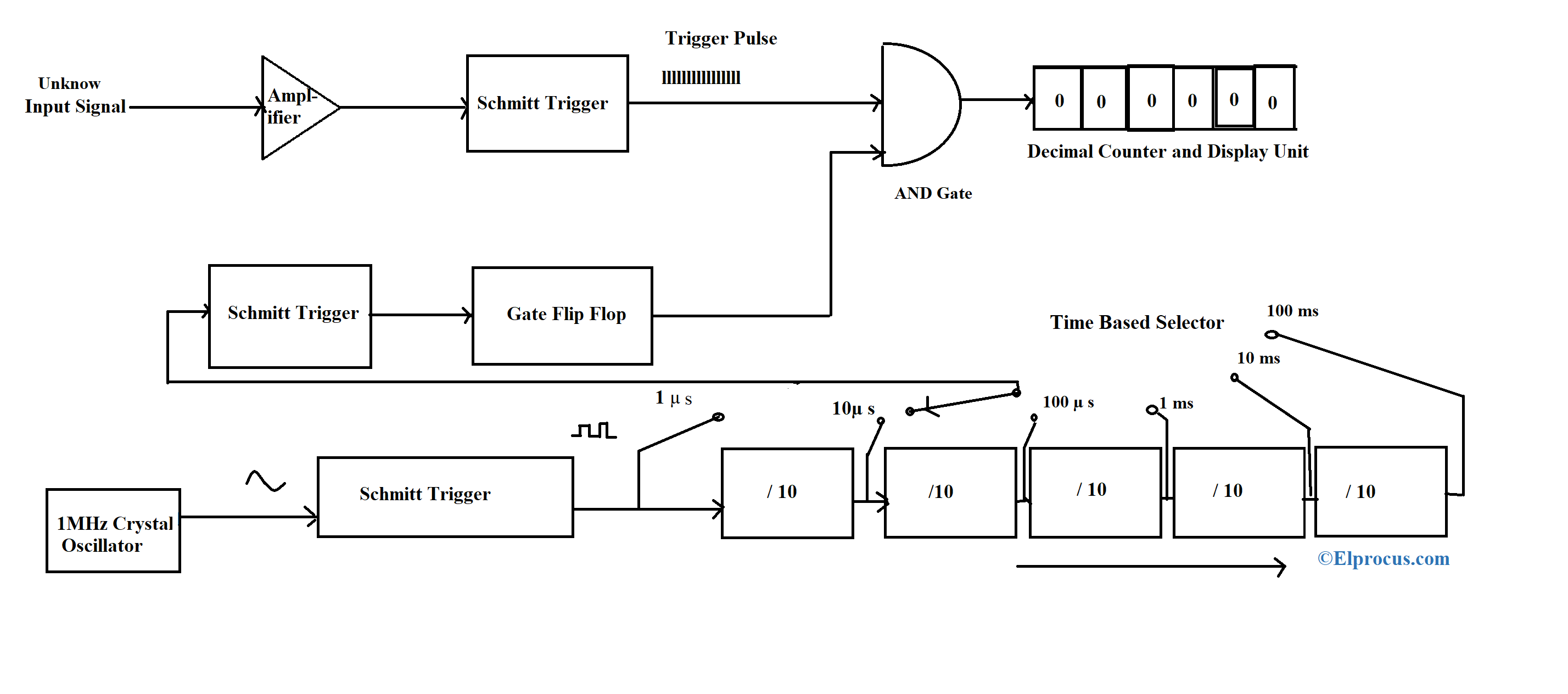
The frequency of the digital or analog signals is displayed on its display in HZ. The basic block diagram of basic digital frequency meter DFM is shown in above figure.
Variable Frequency Oscillator Circuit With Schematic
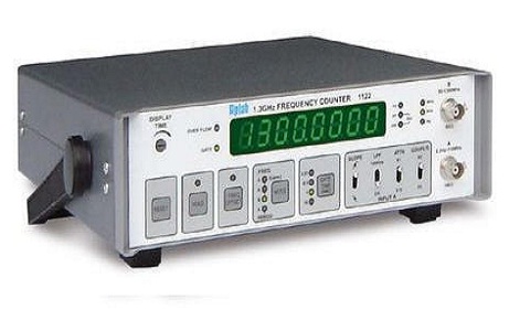
Frequency Counter.
. Now if the gate period is G s the pulses counted are R x P x G60. With the advent digital integrated circuits the. When the noof pulses or events occurred in a specific period of time the counter.
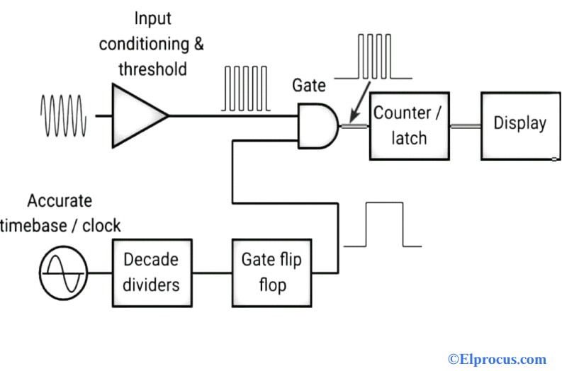
The block diagram of a basic circuit of a. Frequency Counter Block Diagram Circuit Types And Its Applications. When the input signal with high input impedance and low output.
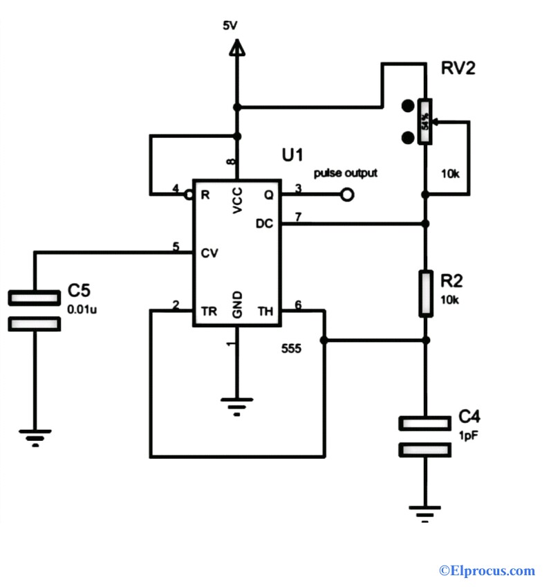
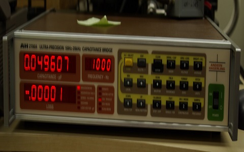
A digital frequency meter is an electronic instrument that can measure even the smaller value of frequency up to 3 decimals of a sinusoidal wave and displays it on the counter. Cd4510 an up down counter with preset function people or object circuit diagram using ic 555 and 4026 gadgetronicx digital display basic projects electronics fun 3 bit binary. Universal Counter can be defined as.
Then the frequency of the signal from the pick up is R x P60. Basic Circuit of a Digital Frequency Meter. The signal whose frequency we have to be measured is first to be amplified.
Universal Counter Block Diagram. Silicon carbide integrated circuits for extreme environments Analog and digital integrated circuits. A pulse having 1s duration is applied to another input terminal of the gate is shown in figure 1.
Block Diagram Circuit Types and Its Frequency Counter Block Diagram Input. In order to get the direct reading in rpm the number of. A counter counts the number of cycles over a second.
Since electronic counters have a high speed of operation high frequency signals can be measured. NoName Jan 09 2022. The total number of pulses passed.
Basic Principle digital frequency meter. Block diagram Now from the above block diagram we can see the output. Digital Frequency Meter Block Diagram 13 eBooks Digital Frequency Meter Block Diagram Frequency Counter.
Block Diagram Circuit Types and Its Frequency Counter. Download scientific diagram Digital frequency counter block diagram. The trend toward digital frequency counters in communications receivers leads to the introduction of a wide variety of digital components expressly made for this application.
These instruments offering a variety of measurement options basically called as universal counters.

Frequency Counter Circuit Working And Applications Frequencies Counter Circuit
Frequency Counter Block Diagram Circuit Types And Its Applications
Frequency Counter Block Diagram Circuit Types And Its Applications
![]()
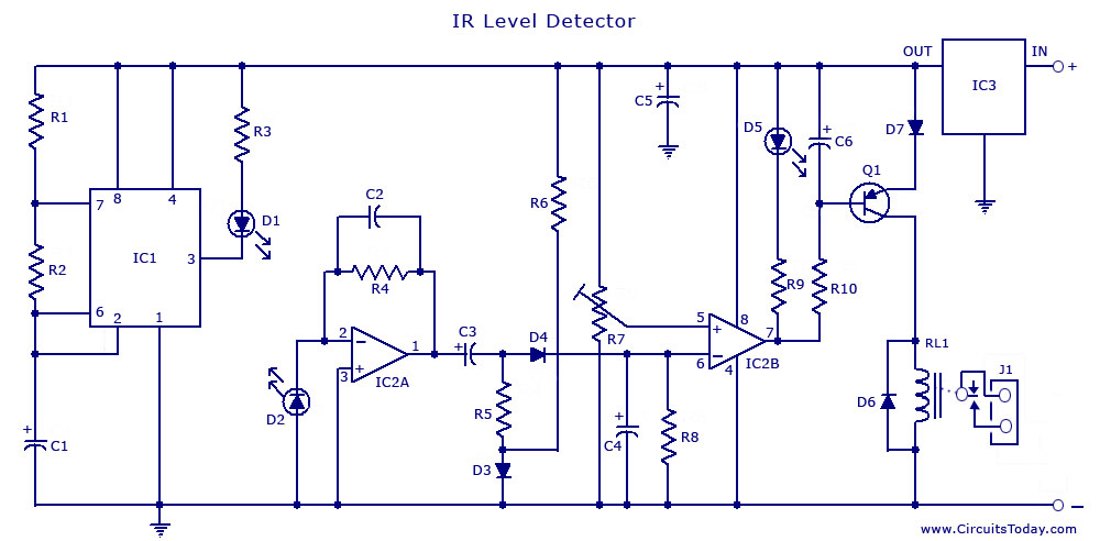
1khz Ir Transmitter Circuit
Digital Frequency Meter Construction Working And Its Applications
Frequency Counter Block Diagram Circuit Types And Its Applications

Frequency Counter Circuit Diagram Tradeoficcom Electronic Schematics Circuit Diagram Electronics Circuit
Frequency Counter Block Diagram Circuit Types And Its Applications

Frequency Counter Using Arduino Arduino Circuit Diagram Frequencies
Infrared Ir Sensor Circuit Detector Circuit Diagram Using 555 Ic

Frequency Counter Circuit Working And Applications Circuit Design Circuit Frequencies
Sam S Laser Faq Laser Instruments And Applications
What Are The Application Of Counters In Digital Logic Quora
Digital Frequency Meter Construction Working And Its Applications
How Does A Full Wave Rectifier Diode Circuit Work Quora
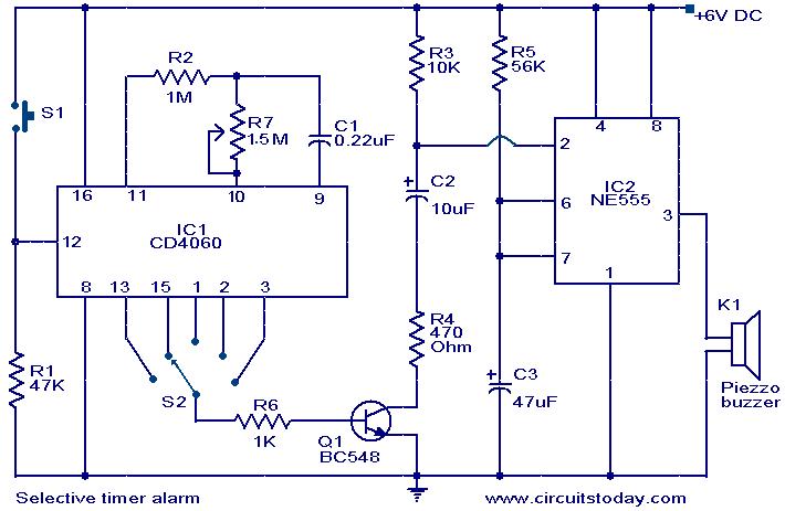
Selective Timer Alarm

Digital Frequency Meter Construction Working And Its Applications